Design Experience With Hole Size, Location Width And Spacing For Heavy Copper PCBs
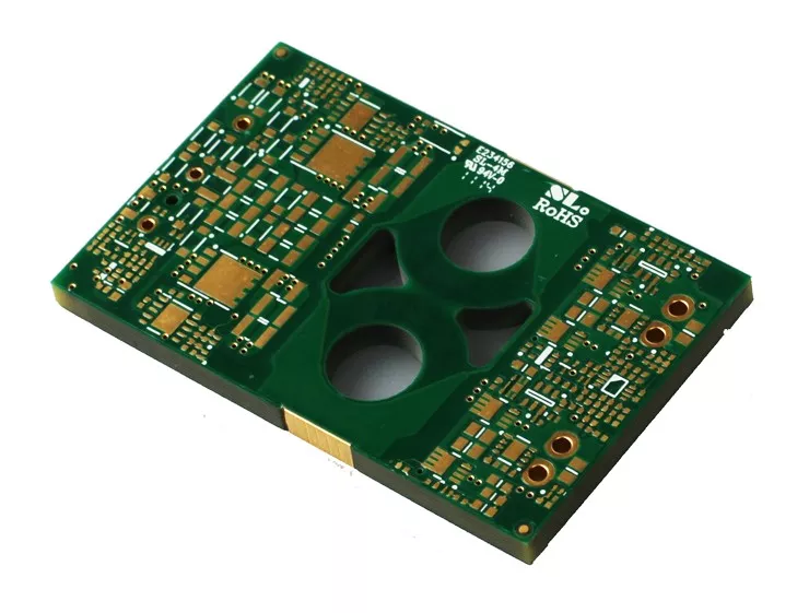
Printed circuit boards (PCBs) can be found in a variety of kinds, one of which amongst SMT producers is the high existing PCB, likewise known as a hefty copper PCB. These units have some helpful attributes for high present and variable temperature level applications. Heavy copper PCBs can resist higher temperatures while handling greater present rates and offering stronger connection points. Hefty copper PCBs are made with 4 or more ounces of copper on each layer. 4-ounce copper PCBs are most frequently made use of in industrial products. Copper concentrations can be as high as 200 ounces per square foot. Heavy copper PCBs are commonly made use of in electronics and circuits that need high-power transmission. On top of that, these PCBs use impressive thermal stamina. The thermal array is essential in several applications, particularly electronic devices, where heats can ruin sensitive digital parts as well as significantly influence circuit performance. Designing PCBs with severe copper plating requires planning as well as mindful consideration of numerous variables that do not take place in the layout of typical light copper boards. Because of uncommon manufacturing obstacles and also non-standard processes connected with these product kinds, numerous suppliers avoid heavy copper and also severe copper board orders completely. Also under the most effective conditions, severe copper motherboard can be a lot more difficult to manufacture than typical. Nevertheless, it is still possible to produce manufacturable layouts by recognizing the troubles inherent in Heavy copper PCB manufacturing. Nevertheless, this huge quantity of copper is used as an option to raising the density of the placement, which is not constantly feasible. Standard PCB placements usually call for a particular size to offer the correct power level while taking into consideration thermal restraints. Thick copper PCBs use thicker alignments yet at a decreased width to do the exact same job. The thickness of the plated holes and also through-hole sidewalls may be enhanced for PCBs with thick copper circuits. The manufacturing process is a little various from that of a conventional PCB, with unique plating and etching methods utilized to accommodate the additional density of the copper. Thick copper PCBs can endure heats (e.g., solder heat) and destructive environments effectively. In these instances, copper PCBs can form a non-toxic passivation layer that safeguards them. This blog post will discuss several of the essential principles of the advanced copper plating procedure to make sure that PCB developers can make sound options for successful production. What is a high-current PCB? High-current PCBs can sustain greater crucial present densities than conventional boards, which may only support double-digit amperage. High-current PCBs can lug hundreds or thousands of amps as well as stand up to greater temperatures for longer periods. Therefore, they supply a solid link factor. The distinct style of these PCBs has thicker, much heavier copper layers that offer the PCBs their resilient features. What is a hefty copper PCB? A heavy copper PCB is a high-current PCB which contains 3 ounces or more of copper in the external as well as internal layers of the board. Even if the overall quantity of copper is less than 3 ounces, if the PCB has a copper density more than 4 ounces per square foot, it is thought about a heavy copper PCB. Polar copper PCBs are normally 10 ounces per square foot or higher. Understanding the Construction of Heavy Copper PCBs Standard published circuit card, whether double-sided or multilayer, are manufactured using a combination of copper etching and also layering processes. Circuit layers begin with thin copper aluminum foil sheets (commonly 0.5 oz/ft 2 to 2 oz/ft 2), are etched to get rid of unwanted copper, and also plated to increase copper density in planes, traces, pads, as well as layered vias. All circuit layers are laminated right into a full plan using an epoxy-based substratum (e.g., FR4 or polyimide). Boards having hefty copper circuits are created similarly, albeit with specialized etching and also plating strategies such as high-speed/step plating as well as differential etching. Historically, thick copper functions were formed exclusively by engraving thick copper-clad laminate material, causing uneven alignment sidewalls as well as unacceptable undercuts. Advancements in layering innovation permit thick copper features to be developed by a combination of plating as well as etching, resulting in straight sidewalls and also minor undercuts. Plating thick copper circuits allow board suppliers to boost the density of copper in the sidewalls of layered holes as well as vias. It is currently possible to mix hefty copper with conventional features on a solitary board, additionally called PowerLink. Advantages include reducedlayer count, reduced insusceptibility power distribution, smaller impact, and potential price financial savings. High current/high power circuits and their control circuits are generally created separately on separate boards. Heavy copper plating allows for the combination of high-current and control circuits, enabling high-density and also basic board frameworks. Design general rules for trace size and spacing for hefty copper PCB When you require to develop a heavy copper PCB, your published circuit board supplier will certainly recommend you on the appropriate trace width as well as spacing for a hefty copper PCB. There might be 2 or more collections of policies for the layout in question because the best determining consider developing the rules is the weight of the base copper, not the weight of the finished copper. While a much heavier base foil (as much as 4 or 6 ounces) may lower plating time, this may be the only benefit. The difficulty with heavy copper PCB positionings is the trapezoidal cross-section as a result of engraving through the thicker base foil. Trapezoidal alignments have much less current bring capability since the top of the placement is narrower than the bottom. Producers may additionally have troubles drilling layered holes via so much copper due to the fact that even more copper makes removing vacuum material throughout the stroke harder. For these factors, PCB suppliers will certainly advise starting with foils created for really light materials, such as half ounces. Although making use of a half-ounce foil to attain a density of 20 ounces would transcend in all respects to utilizing a larger foil. With light foil, narrower placements and smaller sized spaces can be used, so the area available for circuit directing on each layer will certainly raise. An additional advantage is the enhanced high quality of the trace etching. Most significantly, the sidewalls are nearly completely perpendicular to the substratum after engraving due to the fact that the entire sidewall of the positioning is developed by piling the plating. This has the advantage that the cross-sectional location of the positioning is exactly its height multiplied by its size. Consequently, the complete height of the alignment after layering can be developed to be smaller than if much less plating was done on a thicker base aluminum foil and still satisfy the same current-carrying ability. Hefty copper and also board with openings As in standard PCB manufacturing, the plating of the holes and the plating of the circuits are part of a single procedure. For typical PCBs, the amount of copper added is little as well as predictable. The size of the boring tool utilized to develop the plated-through openings (PTH) is typically around 0.003″ – 0.006″ larger than the called for finish opening dimension (FHS). The quantity of oversizing depends on the maker’s process control and the last surface that will be used. The hole will certainly be closed to its nominal last diameter throughout machining between the plated copper as well as the surface finish. Heavy copper differs from polar copper. For boards plated with heavy copper as well as polar copper, it is generally difficult to pierce the holes to the larger size needed to finish the holes near to their nominal diameter. As an example, a 20 oz. PCB surface obtains around 0.028″ of added copper. The holes get a comparable amount. As opposed to adding 0.005″ to the drill size before plating, as is done on light copper boards, virtually 0.060″ need to be added to the density of such openings. It is simple to think of the destructive result of including 0.060 inches to the annulus of each hole in the style; it would severely minimize the surface area available for circuit directing. In addition to this obvious trouble, the quantity of layering gotten by each PTH ends up being even more random. It is very unlikely that a tolerance of +/- 0.003″ will be achieved at every location on the board. What is the option? The option is to redrill the holes after plating however before surface area prep work. Redrilling removes the excess copper build-up and therefore recovers the hole to the correct nominal diameter. This functions well and also sounds like an excellent solution, however as with every little thing pertaining to extreme copper, there are pitfalls and constraints. The major trouble is that the center of the hole will certainly not be close to a level surface area that easily approves a rotating drill bit. Instead, the plating tends to be somewhat rounded and also recessed, with a fairly small open location in its facility. When the little bits encounter surfaces smaller than the flat surface area, they deflect; when carbide bits disperse, they crack. To address this issue, the strategy is to use completed opening sizes starting at 0.050.” Drills in this variety are generally strong enough to stand up to influence with scooped surfaces as long as the feed as well as RPM settings are changed for this non-standard application. For openings where you do not intend to fit parts or wires, you can make use of smaller sized openings and enable the supplier to plate them with a shut (or near-closed) shape. Even if these holes are nothing more than through openings, it is still a great concept to make them larger than regular via openings. This is especially real for several layers, which can be heavier than normal copper weight inside. Despite the variety of layers, a good rule of thumb for extreme copper sheets is to use through-holes drilled before layering that is no smaller than 0.025″ and preferably 0.030″ or larger. Summary Extreme copper PCBs are never ever completely created or produced as a regular. This is since every irregular attribute might influence various other functions. An option to one style requirement may present overwhelming troubles in another location. Save for a rainy day. Enable even more time in both the layout and production cycles. Initially, ask concerns. Your PCB maker can keep you out of possible stumbling blocks early in the cycle. Submit a preliminary variation of the format for layout for manufacturing (DFM) evaluation to identify locations for renovation. The outcome of a partnership between the PCB developer and supplier should be a severe copper board that is highly practical and also reputable.
Design Experience With Hole Size, Location Width And Spacing For Heavy Copper PCBs Read More »

