- How the four-layer FPC was born
- Comparison between the four-layer FPC circuit board and PCB
- The structure of the four-layer FPC soft board
- Primary raw materials for four-layer FPC soft board manufacturing
- Four-layer FPC soft board processing process
- What control impedance can the four-layer FPC soft board require?
- Need Someone to Manufacture Your PCB? Anpllopcb can help!
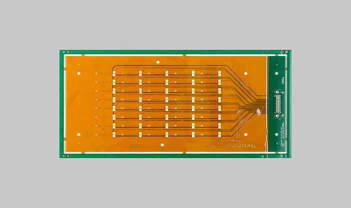
Flexible printed circuit boards, or FPCBs, are a type of circuit board made to be flexible and able to bend. This makes them useful in various applications where a rigid circuit board would not be able to be used, such as in electronic devices that need to be bent or flexed or in devices that need to be lightweight and compact.
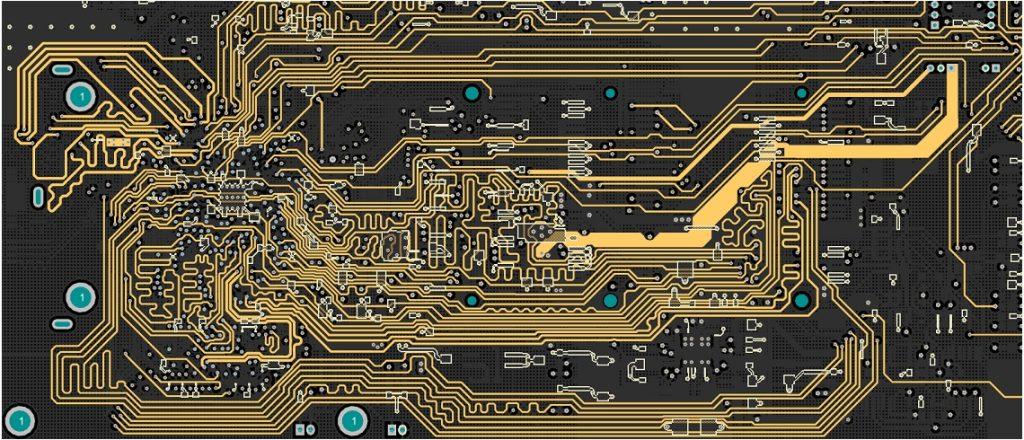
A four-layer FPC soft board is a type of FPCB with four layers of conductive material, typically made of copper. This allows for more complex circuits to be created on the board, with multiple layers of conductive traces that can connect different components on the board. This can make the board more efficient and help reduce the amount of space needed to accommodate the circuit.
In general, using a four-layer FPC soft board can provide several benefits over other circuit boards. For example, it can help to save space, reduce weight, and make the circuit more efficient. It can also be more flexible and withstand bending and flexing, making it useful in many applications.
How the four-layer FPC was born
Flexible printed circuit boards, or FPCBs, were first developed in the 1960s to make circuits more compact and efficient. At the time, most courses were made using traditional printed circuit boards made of rigid, non-flexible materials. These boards were limited in their ability to be bent or flexed, which made them difficult to use in specific applications.
The first FPCBs were made using a single layer of conductive material, typically copper, bonded to a flexible plastic substrate. This allowed the circuit to be flexible but was limited in its ability to accommodate complex circuits. As technology and manufacturing processes advanced, creating FPCBs with multiple layers of conductive material became possible. This made more complex circuits and led to the development of four-layer FPC soft boards.
Today, four-layer FPC soft boards are widely used in various electronic devices, including smartphones, tablets, and other portable devices. They are also used in other applications, such as automotive electronics and medical devices. The ability to create flexible, lightweight, and efficient circuits makes four-layer FPC soft boards an essential component in the design and production of many electronic devices.
Comparison between the four-layer FPC circuit board and PCB
A four-layer FPC soft board is a flexible printed circuit board, or FPCB, with four layers of conductive material, typically made of copper. This allows for creating complex circuits on the board, with multiple layers of conductive traces that can connect different components.
A printed circuit board, or PCB, is a type of circuit board made of rigid, non-flexible materials. It typically has one or more layers of conductive material, also made of copper, used to create the circuit.
There are several critical differences between four-layer FPC circuit boards and PCBs. The most obvious difference is that FPCBs are flexible and can be bent or flexed, while PCBs are rigid and cannot be bent. This makes FPCBs useful in applications where a flexible circuit is needed, such as in electronic devices that need to be bent or flexed or in devices that need to be lightweight and compact.
Another key difference is that FPCBs can accommodate more complex circuits than PCBs. This is because they can have multiple layers of conductive material, allowing for the creation of courses with more connections and components. This can make FPCBs more efficient and help reduce the amount of space needed to accommodate the circuit.
Four-layer FPC circuit boards are generally helpful in applications where a flexible, lightweight, and efficient circuit is needed. They are commonly used in portable electronic devices, such as smartphones and tablets, as well as in automotive electronics and medical devices. On the other hand, PCBs are more commonly used in applications where a rigid circuit is needed, such as in computers and other electronic devices that do not need to be bent or flexed.
The structure of the four-layer FPC soft board
A four-layer FPC soft board is a flexible printed circuit board with four layers of conductive material, typically made of copper. These layers are sandwiched between two insulating layers, typically made of a flexible, heat-resistant plastic such as polyimide.
The four layers of conductive material are arranged in the following way:
1. The first layer is the outer layer, typically called the “overlay” layer. This layer protects the other layers of the circuit board and is generally made of a flexible, heat-resistant material such as polyimide.
2. The second layer is the “signal layer,” where the circuit traces are located. This layer is typically made of copper and is where the electrical connections between different components on the circuit board are made.
3. The third layer is the “ground layer,” which provides a standard ground reference for the circuit. This layer is also typically made of copper and is used to connect different components on the circuit board to a common ground point.
4. The fourth layer is the “power layer,” which provides power to the circuit board’s different components. This layer is typically copper and connects members to the power source.
The four layers of conductive material are sandwiched between two layers of insulating material, which provide electrical isolation and protect the conductive layers from damage. This allows the circuit to be flexible and withstand bending and flexing without breaking. The four-layer FPC soft board is typically held together using a bonding process, such as lamination or adhesive bonding, to create a durable, flexible circuit board.
Primary raw materials for four-layer FPC soft board manufacturing
The primary raw materials used in manufacturing four-layer FPC soft boards are conductive materials, such as copper, and insulating materials, such as polyimide.
The conductive materials are typically used to create the layers of the circuit board that carry the electrical signals and power. Copper is the most commonly used conductive material, as it is highly conductive, flexible, and easy to work with. Some conductive materials, such as aluminum or silver, may also be used.
The insulating materials are used to provide electrical isolation and protect the conductive layers of the circuit board. Polyimide is the most commonly used insulating material for FPCBs, as it is flexible, heat-resistant, and has good electrical insulation properties. In some cases, other insulating materials, such as epoxy or acrylic, may also be used.
In addition to the conductive and insulating materials, other raw materials may also be used to manufacture four-layer FPC soft boards. These may include adhesives for bonding the different layers of the circuit board together and protective coatings to provide additional durability and protection for the circuit board.
Four-layer FPC soft board processing process
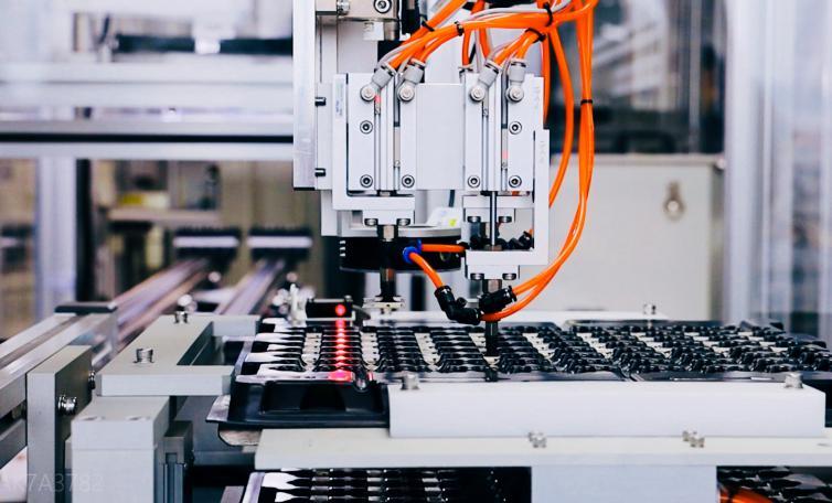
The processing of a four-layer FPC soft board typically involves several steps, which may vary depending on the specific manufacturing process used. In general, the process can be divided into the following steps:
1. The first step is to create the layers of the circuit board. This typically involves creating the conductive layers, usually made of copper, and the insulating layers, which generally are made of a flexible, heat-resistant plastic such as polyimide.
2. The next step is to bond the layers together to create the final circuit board. This may be done using a lamination process, in which the layers are heated, and pressure is applied to bond them. Alternatively, an adhesive bonding process may be used, in which an adhesive is applied to the layers and allowed to cure to bond them together.
3. Once the circuit board has been bonded together, the next step is to create the circuit traces on the conductive layers. This typically involves using a photolithography process. A pattern of the circuit traces is made on a photomask and then transferred to the conductive layers using light and chemicals.
4. The next step is to etch the circuit traces onto the conductive layers. This typically involves using a chemical etching process, in which the exposed areas of the conductive layers are removed, leaving only the desired circuit traces.
5. After the circuit traces have been created, the next step is to apply a protective coating to the circuit board. This may be done using a coating process, in which a protective material is applied to the surface of the circuit board to provide additional durability and protection.
6. The final step is to test the circuit board to ensure it functions correctly. This may involve testing the electrical characteristics of the circuit, such as its resistance and capacitance, and ensuring that it can carry the required electrical signals without any errors or problems.
Overall, the processing of a four-layer FPC soft board is a complex and multi-step process that involves the use of specialized equipment and materials. The exact process may vary depending on the manufacturing process and the requirements of the final circuit board.
What control impedance can the four-layer FPC soft board require?
The control impedance of a four-layer FPC soft board is the electrical resistance of the circuit traces on the board and is typically measured in ohms. The control impedance of a circuit board is an essential factor in determining its performance and reliability, as it affects the ability of the circuit to carry electrical signals without errors or losses.
The manufacturer or designer of the board typically specifies the control impedance of a four-layer FPC soft board. It can vary depending on the specific application and requirements of the circuit. A lower control impedance is generally desired, as it allows the course to carry electrical signals more efficiently and with less loss. However, lower control impedance may also require thicker conductive layers, which can increase the size and weight of the circuit board.
In general, the control impedance of a four-layer FPC soft board may range from around 50 ohms to over 100 ohms, depending on the specific requirements of the circuit. The same control impedance that is required will depend on the particular application and the characteristics of the components that are used on the circuit board.
Need Someone to Manufacture Your PCB? Anpllopcb can help!
As you can see, much work goes into the printed circuit board manufacturing process. To guarantee PCBs are manufactured with your expected quality, performance, and durability, you have to pick a Manufacturer who has a high level of expertise and a focus on quality at each stage.
With the idea that our client’s success measures our success, we focus on the care and attention to detail that each PCB manufacturing step requires. We also offer vacuum packaging, weighing, and delivery to ensure your PCB order arrives safely and without damage. Up to now, we have printed circuit boards for companies of all sizes from over 80 countries, and we aim to deliver our manufactured PCBs to every corner of the world in the coming years.
We offer quick-turn PCB prototypes, mass PCB production, and assembly services. The quotation is always fast and FREE.


